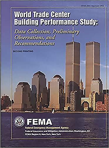

World Trade Center building performance study : data collection, preliminary observations, and recommendations [report editor, Therese McAllister ; chapter leaders and authors, Gene Corley ... et al.] txt
Washington, DC Federal emergency management agency 2002Descripción: 1 v. (various pagings) col. ill. 28 cmTipo de contenido:- text
- unmediaded
- volume
- 0160673895
- World TRade Center New York, N.Y. -- Design and construction
- Skyscraper -- New York (State) -- New York -- Design and construction
- September 11 Terrorist Attacks , 2001
- Office buildings -- Fires and fire prevention -- New York (State) -- New York
- Tall buildings -- Fires and fire prevention -- New York (State) -- New York
- Building failures -- New York (State) -- New York
- HD7293 L5567 2002
- Also available via Internet from the web site. Address as of 6/06/02 : http://www.house.gov/science/hot/wtc/wtcreport.htm ; current access is available via PURL
| Imagen de cubierta | Tipo de ítem | Biblioteca actual | Biblioteca de origen | Colección | Ubicación en estantería | Signatura topográfica | Materiales especificados | Info Vol | URL | Copia número | Estado | Notas | Fecha de vencimiento | Código de barras | Reserva de ítems | Prioridad de la cola de reserva de ejemplar | Reservas para cursos | |
|---|---|---|---|---|---|---|---|---|---|---|---|---|---|---|---|---|---|---|
| Libro | Biblioteca Encarnación Valdés Colección General bev | 720.4837471 W92711 (Navegar estantería(Abre debajo)) | 2002 | Disponible | 80000002201948 | |||||||||||||
| Libro | CARIBET Biblioteca Arquitectura Colección General CARIBET | General HD7293 L567 2002 (Navegar estantería(Abre debajo)) | 1 | Disponible | 91000000015552 |
Descripciones mejoradas de Syndetics:
NOTE: NO FURTHER DISCOUNT FOR THIS PRINT PRODUCT--OVERSTOCK SALE -- Significantly reduced list price while supplies last
Examines the damage to the World Trade Center and surrounding buildings caused by the events of September 11, 2001. Also identifies additional studies that should be performed.
This illustrated report presents observations, findings, and recommendations regarding the performance of buildings affected by the September 11 attacks on the WTC towers in New York City. The report examines the performance of the buildings under extreme conditions, determines the probable causes of collapse, and identifies lessons to be learned. It makes recommendations for more detailed engineering studies to complete the assessments and produce improved guidelines for building design and performance evaluation tools.
Engineers, especially structural engineers and construction teams, emergency response personnel, fire managmenet professionals, and building architects may be interested in this volume. American citizens and students interested in these fields along with people living and working in skyscrapers or multi-level/floor buildings may be interested in this research.
Related products:
Terrorism and 9/11 history resources collection is available here: https://bookstore.gpo.gov/catalog/us-military-history/terrorism-911-history
Emergency Management and First Responders collection is available here: https://bookstore.gpo.gov/catalog/security-defense-law-enforcement/emergency-management-first-responders
Other products produced by the U.S. Department of Homeland Security, Federal Emergency Management Agency (FEMA) can be found here: https://bookstore.gpo.gov/agency/528
"Produced by Greenhorne & O' Mara, Inc. (G&O) under contract EMW-99-CO-0267"- - T.p. verso
Includes bibliographical references
Table of Contents:
Executive Summary --
1 Introduction --
1.1 Purpose and Scope of Study 1-1 --
1.2 WTC Site 1-2 --
1.3 Timeline and Event Summary 1-4 --
1.4 Response of the Engineering Community 1-8 --
1.4.1 Local Authorities 1-8 --
1.4.2 SEAoNY Participation 1-10
1.5 Overview of Building Codes and Fire Standards 1-15 --
1.5.1 Building Codes 1-15 --
1.5.2 Unusual Building Loads 1-16 --
1.5.3 Overview of Fire Structure Interaction 1-17 --
1.5.3.1 ASTM E119 Standard Fire Test 1-18 --
1.5.3.2 Performance in Actual Building Fires 1-18 --
1.6 Report Organization 1-20 --
1.7 References 1-21 --
2 WTC 1 and WTC 2 --
2.1 Building Descriptions 2-1 --
2.1.1 General 2-1 --
2.1.2 Structural Description 2-1 --
2.1.3 Fire Protection --
2.1.3.1 Passive Protection 2-12 --
2.1.3.2 Suppression 2-12 --
2.1.3.3 Smoke Management 2-13 --
2.1.3.4 Fire Department Procedures 2-13 --
2.1.4 Emergency Egress 2-13 --
2.1.5 Emergency Power 2-14 --
2.1.6 Management Procedures 2-14 --
2.2 Building Response 2-15 --
2.2.1 WTC 1 2-15 --
2.2.1.1 Initial Damage From Aircraft Impact 2-15 --
2.2.1.2 Fire Development 2-15 --
2.2.1.3 Evacuation 2-21 --
2.2.1.4 Structural Response to Fire Loading 2-24 --
2.2.1.5 Progression of Collapse 2-27 --
2.2.2 WTC 2 2-27 --
2.2.2.1 Initial Damage From Aircraft Impact 2-27 --
2.2.2.2 Preliminary Structural Analysis 2-32 --
2.2.2.3 Fire Development 2-34 --
2.2.2.4 Evacuation 2-35 --
2.2.2.5 Initiation of Collapse 2-35 --
2.2.2.6 Progression of Collapse 2-35 --
2.2.3 Substructure 2-35 --
2.3 Observations and Findings 2-36 --
2.4 Recommendations 2-39 --
2.5 References 2-40 --
3 WTC 3 --
3.1 Design and Construction Features 3-1 --
3.2 1993 Attack 3-5 --
3.3 2001 Attacks 3-5 --
3.3.1 Fire and Evacuation 3-5 --
3.3.2 Building Response 3-6 --
3.4 Observations 3-8 --
3.5 Recommendations 3-8 --
3.5 References 3-8 --
4 WTC 4 , 5, and 6 --
4.1 Design and Construction Features 4-1 --
4.1.1 Structural Design Features 4-1 --
4.1.2 Fire Protection Features 4-2 --
4.2 Building Loads and Performance 4-4 --
4.2.1 Impact Damage to WTC 5 4-7 --
4.2.2 Fire Damage 4-9 --
4.3 Analysis of Building Performance 4-10 --
4.3.1 Steel and Frame Behavior 4-10 --
4.3.2 WTC 5 Local Collapse Mechanisms 4-12 --
4.4 Observations and Findings 4-16 --
4.5 Recommendations 4-21 --
4.6 References 4-21 --
5 WTC 7 --
5.1 Introduction 5-1 --
5.2 Structural Description 5-3 --
5.2.1 Foundations 5-3 --
5.2.2 Structural Framing 5-4 --
5.2.3 Transfer Trusses and Girders 5-4 --
5.2.4 Connections 5-8 --
5.3 Fire Protection Systems 5-10 --
5.3.1 Egress Systems 5-10 --
5.3.2 Detection and Alarm 5-10 --
5.3.3 Compartmentalization 5-11 --
5.3.4 Suppression Systems 5-12 --
5.3.5 Power 5-13 --
5.4 Building Loads 5-13 --
5.5 Timeline of Events Affecting WTC 7 on September 11 , 2001 5-16 --
5.5.1 Collapse of WTC 2 5-16 --
5.5.2 Collapse of WTC 1 5-16 --
5.5.3 Fires at WTC 7 5-20
5.5.4 Sequence of WTC 7 Collapse 5-23 --
5.6 Potential Collapse Mechanism 5-24 --
5.6.1 Probable Collapse Initiation Events 5-24 --
5.6.2 Probable Collapse Sequence 5-30 --
5.7 Observations and Findings 5-31 --
5.8 Recommendations 5-32 --
5.9 References 5-32 --
6 Bankers Trust Building --
6.1 Introduction 6-1 --
6.2 Building Description 6-1 --
6.3 Structural Damage Description 6-4 --
6.4 Architectural Damage Description 6-6 --
6.5 Fireproofing 6-10 --
6.6 Overall Assessment 6-10 --
6.7 Analysis 6-11 --
6.7.1 Key Assumptions 6-12 --
6.7.2 Model Refinement 6-12 --
6.7.3 Simulation of Nonlinear Behavior 6-13 --
6.7.4 Connection Details 6-13 --
6.7.5 Connection Behavior 6-14 --
6.8 Observations and Findings 6-15 --
6.9 Recommendations 6-16 --
6.10 References 6-16 --
7 Peripheral Buildings --
7.1 Introduction 7-1 --
7.2 World Financial Center 7-4 --
7.2.1 The Winter Garden 7-4 --
7.2.2 WTC 3, American Express Building 7-5 --
7.3 Verizon Building 7-7 --
7-4 30 West Broadway 7-13 --
7.5 130 Cedar Street 7-14 --
7.6 90 West Street 7-15 --
7.7 45 Park Place 7-17 --
7.8 One Liberty Plaza 7-17 --
7.9 Observations and Findings 7-19 --
7.10 Recommendations 7-19 --
7.11 References 7-19 --
8 Observations, Findings, and Recommendations --
8.1 Summary of Report Observations , Findings and Recommendations 8-1 --
8.2 Chapter Observations , Findings , and Recommendations 8-2 --
8.2.1 Chapter 1 : Building Codes and Fire Standards 8-2 --
8.2.2 Chapter 2. WTC 1 and WTC 2 8-2 --
8.2.2.1 Observations and Findings 8-2 --
8.2.2.2 Recommendations 8-5 --
8.2.3 Chapter 3: WTC 3 8-6 --
8.2.3.1 Observations 8-6 --
8.2.3.2 Recommendations 8-6 --
8.2.4 Chapter 4: WTC 4 , 5 , and 6 8-6 --
8.2.4.1 Observations and Findings 8-6 --
8.2.4.2 Recommendations 8-7 --
8.2.5 Chapter 5: WTC 7 8-7 --
8.2.5.1 Observations and Findings 8-7 --
8.2.5.2 Recommendations 8-8 --
8.2.6 Chapter 6: Bankers Trust 8-8 --
8.2.6.1 Observations and Findings 8-8 --
8.2.6.2 Recommendations 8-9 --
8.2.7 Chapter 7: Perpheral Buildings 8-10 --
8.2.7.1 Observations and Findings 8-10 --
8.2.7.2 Recommendations 8-10 --
8.2.8 Appendix C: Limited Metallurgical Examination 8-10 --
8.2.8.1 Observations and Findings 8-10 --
8.2.8.2 Recommendations 8-11 --
8.3 Building Performance Study Recommendations for Future Study 8-11 --
8.3.1 National Response 8-11 --
8.3.2 Interaction of Structural Elements and Fire 8-11 --
8.3.3 Interaction of Professions in Design 8-12 --
8.3.4 Fire Protection Engineering Discipline 8-12 --
8.3.5 Building Evacuation 8-12 --
8.3.6 Emergency Personnel 8-12 --
8.3.7 Education of Stakeholders 8-13 --
8.3.8 Study Process 8-13 --
8.3.9 Archival Information . 8-13 --
8.3.10 SEANY Structural Engineering Emergency Response Plan 8-13 --
A Overview of Fire Protection in Buildings --
A.1 Introduction A.2 Fire Behavior A-1 --
A.2.1 Burning Behavior of Materials A-1 --
A.2.2 Stages of Fire Development A-1 --
A.2.3 Behavior of Fully Developed Fires A-4 --
A.3 Structural Response to Fire A-4 --
A.3.1 Effect of Fire on Steel A-5 --
A.3.1.1 Introduction A-5 --
A.3.1.2 Evaluating Fire Resistance . A-5 --
A.3.1.3 Response of High-rise, Steel-frame Buildings in Previous Fire Incidents A-6 --
A.3.1.4 Properties of Steel A-9 --
A.3.1.5 Fire Protection Techniques for Steel A-10 --
A.3.1.6 Temperature Rise in Steel A-14 --
A.3.1.7 Factors Affecting Performance of Steel Structures in Fire A-14 --
A.3.2 Effect of Fire on Concrete A-17 --
A.3.2.1 General A-19 --
A.3.2.2 Properties of Lightweight Concrete A-19 --
A.3.3 Fire and Structural Modeling A-19 --
A.4 Life Safety A-22 --
A.4.1 Evacuation Process A-23 --
A.4.2 Analysis , A-24 --
A.5 References A-24 --
B Structural Steel and Steel Connections A-26 --
B.1 Structural Steel B-1 --
B.2 Mechanical Properties B-2 --
B.3 WTC 1 and WTC 2 Connection Capacity B-4 --
B.3.1 Background B-4 --
B.3.2 Observations B-5 --
B.3.3 Connectors B-5 --
B.4 Examples of WTC 1 and WTC 2 Connection Capacity B-7 --
B.4.1 Bolted Column End Plates B-7 --
B.4.2 Bolted Spandrel Connections B-8 --
B.4.3 Floor Truss Seated End Connections at Spandrel Beam and Core B-9 --
B.4.4 WTC 5 Column-tree Shear Connections B-12 --
B.5 References B-14 --
C Limited Metallurgical Examination C-1 --
C.1 Introduction C.2 Sample 1 (From WTC 7) C-1 --
C.3 Summary for Sample 1 C-5 --
C.4 Sample 2 (From WTC 1 or WTC 2) C-5 --
C.5 Summary for Sample 2 C-13 --
C.6 Suggestions for Future Research. C-13 --
D WTC Steel Data Collection D-1 --
D.1 Introduction D-1 --
D.2 Project Background D-2 --
D.3 Methods. D-2 --
D.3.1 Identifying and Saving Pieces D-5 --
D.3.2 Documenting Pieces D-8 --
D.3.3 Getting Coupons D-10 --
D.4 Data Collected D-13 --
D.5 Conclusions and Future Work D-13 --
D.6 References Aircraft Information General Specifications E-1 --
F Structural Engineers Emergency Response Plan --
G Acknowledgments --
H Acronyms and Abbreviations --
I Metric Conversions --
Tables --
Table 1.1 Timeline of Major Events 1-10 --
Table 2.1 Estimated Openings in Exterior Walls of WTC 1 2-23 --
Table 5.1 WTC 7 Tenants 5-2 --
Table 5.2 WTC 7 Fuel Distribution Systems 5-14 --
Table 7.1 DoB/SEANY Cooperative Building Damage Assessment - November 7, 2001 7-3 --
Table A.1 Peak Heat Release Rates of Various Materials ( NFPA 92B and NFPA 72 ) A-3 --
Table A.2 Fire Duration in Previous Fire Incidents in Steel-frame Buildings A-10 --
Table A.3 Critical Temperatures for Various Types of Steel A-15 --
Table A.4 Test Methods for Spray-applied Fireproofing Materials A-18 --
Figures --
Chapter 1 --
Figure 1-1 WTC site map 1-3 --
Figure 1-2 Approximate flight paths of aircraft 1-5 --
Figure 1-3 WTC impact locations and resulting fireballs 1-5 --
Figure 1-4 Areas of aircraft debris impact 1-6 --
Figure 1-5 Fireball erupts on the north face of WTC 2 as United Airlines Flight 175 strikes the building 1-7 --
Figure 1-6 View of the north and east faces showing fire and impact damage to both towers 1-7 --
Figure 1-7 Schematic depiction of areas of collapse debris impact, based on aerial photographs and documented damage 1-9 --
Figure 1-8 Seismic recordings on east-west component at Palisades , NY , for events 1-9 at WTC on September 11 , 2001 , distance 34 km 1-11 --
Figure A Satellite photograph of the WTC site taken before the attacks. 1-12 --
Figure 1-9B Satellite photograph of the WTC site taken after the attacks 1-13 --
Figure 1-10 Comparison of high-rise building and aircraft sizes 1-19 --
Chapter 2 --
Figure 2-1 Representative floor plan (based on floor plan for 94th and 95th floors of WTC 1) 2-2 --
Figure 2-2 Representative structural framing plan, upper floors. 2-4 --
Figure 2-3 Partial elevation of exterior bearing-wall frame showing exterior wall module construction 2-6 --
Figure 2-4 Base of exterior wall frame 2-7 --
Figure 2-5 Structural tube frame behavior 2-7 --
Figure 2-6 Floor truss member with details of end connections 2-8 --
Figure 2-7 Erection of prefabricated components, forming exterior wall and floor deck units 2-9 --
Figure 2-8 Erection of floor framing during original construction. 2-9 --
Figure 2-9 Cross-section through main double trusses, showing transverse truss. 2-9 --
Figure 2-10 Outrigger truss system at tower roof. 2-10 --
Figure 2-11 Location of subterranean structure... 2-11 --
Figure 2-12 Floor plan of 94th and 95th floors of WTC 1 showing egress stairways 2-14 --
Figure 2-13 Zone of aircraft impact on the north face of WTC 1. 2-16 --
Figure 2-14 Approximate zone of impact of aircraft on the north face of WTC 1. 2-17 --
Figure 2-15 Impact damage to the north face of WTC 1 2-18 --
Figure 2-16 Impact damage to exterior columns on the north face of WTC 1 2-18 --
Figure 2-17 Approximate debris location on the 91st floor of WTC 1 2-19 --
Figure 2-18 Landing gear found at the corner of West and Rector Streets 2-19 --
Figure 2-19 Redistribution of load after aircraft impact. 2-20 --
Figure 2-20 Expansion of floor slabs and framing results in outward deflection of columns and potential overload 2-25 --
Figure 2-21 Buckling of columns initiated by failure of floor joist connections 2-26 --
Figure 2-22 Catenary action of floor framing on several floors initiates column buckling failures. 2-26 --
Figure 2-23 Aerial photograph of the WTC site after September 11 attack showing adjacent buildings damaged by debris from the collapse of WTC 1 2-28 --
Figure 2-24 Southeast corner of WTC 2 shortly after aircraft impact. 2-28 --
Figure 2-25 Approximate zone of impact of aircraft on the south face of WTC 2. 2-29 --
Figure 2-26 Impact damage to the south and east faces of WTC 2 2-30 --
Figure 2-27 Impact damage to exterior columns on the south face of WTC 2. 2-30 --
Figure 2-28 Conflagration and debris exiting the north wall of WTC 2, behind WTC 1. 2-31 --Figure 2-29 A portion of the fuselage of United Airlines Flight 175 on the roof of WTC 5 2-32
Figure 2-30 North face of WTC 2 opposite the zone of impact on the south face, behind WTC 1. 2-33 --
Figure 2-31 Plot of column utilization ratio at the 80th floor of WTC 2, viewed looking outward.... The top portion of WTC 2 falls to the east, then south, as viewed from 2-34 --
Figure 2-32 the northeast. 2-36 --
Chapter 3 --
Figure 3-1 Developed north and west elevations. 3-2 --
Figure 3-2 Developed south and east elevations. 3-2 --
Figure 3-3 Typical hotel floor plan. 3-3 --
Figure 3-4 Typical hotel floor framing plan. 3-4 --
Figure 3-5 Typical transverse bracing elevation. 3-5 --
Figure 3-6 Exterior columns from the collapse of WTC 2 falling on the southern part of WTC 3 3-6 --
Figure 3-7 Partial collapse of WTC 3 after collapse of WTC 2. 3-7 --
Figure 3-8 Remains of WTC 3 after collapse of WTC 1 and WTC 2 3-8 --
Chapter 4 Figure 4-1 Typical floor plan for WTC 5. 4-2 --
Figure 4-2 Typical column-tree system (not to scale) 4-3 --
Figure 4-3 Typical interior bay framing in WTC 5. 4-3 --
Figure 4-4 Stairway enclosure core locations in WTC 5 4-4 --
Figure 4-5 Damage to WTC 4 4-5 --
Figure 4-6 Damage to WTC 5 4-5 --
Figure 4-7 Approximate locations of damaged floor areas in WTC 5 4-6 --
Figure 4-8 Damage to WTC 6 4-8 --
Figure 4-9 Impact damage to WTC 6 4-8 --
Figure 4-10 Impact damage to the exterior façade of WTC 6 4-9 --
Figure 4-11 WTC 5 façade damage 4-10 --
Figure 4-12 Impact damage to WTC 5 4-11 --
Figure 4-13 WTC 5 on fire 4-13 --
Figure 4-14 Deformed beams in WTC 5 4-13 --
Figure 4-15 Unburned bookstore in WTC 5 4-14 --
Figure 4-16 Looking through the door into the undamaged stair tower in WTC S 4-14 --
Figure 4-17 Buckled beam flange and column on the 8th floor of WTC 5 that was weakened by fire 4-15 --
Figure 4-18 Internal collapsed area in WTC 5 4-16 --
Figure 4-19 Internal collapsed area in WTC 5 4-17 --
Figure 4-20 Internal collapsed area in WTC 5 4-18 --
Figure 4-21 Internal collapsed area in WTC 5 with closeup of connection failure at column tree 4-18 --
Figure 4-22 Connection samples 4-19 --
Chapter 5 --
Figure 5-1 Foundation plan - WTC7 5-3 --
Figure 5-2 Plan view of typical floor framing for the 8th through 45th floors 5-4 --
Figure 5-3 Elevations of building and core area 5-5 --
Figure 5-4 Fifth floor diaphragm plan showing T-sections embedded in 14-inch slab 5-6 --
Figure 5-5 3-D diagram showing relations of trusses and transfer girders 5-6 --
Figure 5-6 Seventh floor plan showing locations of transfer trusses and girders 5-7--
Figure 5-7 Truss 1 detail 5-8 --
Figure 5-8 Truss 2 detail 5-9 --
Figure 5-9 Truss 3 detail 5-10
Figure 5-10 Cantilever transfer girder detail 5-11 --
Figure 5-11 Compartmentalization provided by concrete floor slabs 5-12 -- --
Figure 5-12 Sequence of debris generated by collapses of WTC 2, 1, and 7 5-17 --
Figure 5-13 Pedestrian bridge (bottom center) still standing after WTC 2 has collapsed, sending substantial dust and debris onto the street, but before WTC 1 (top center) has collapsed 5-18 --
Figure 5-14 View from the north of the WTC 1 collapse and the spread of debris around WTC7 5-18 --
Figure 5-15 Debris from the collapse of WTC 1 located between WTC 7 (left) and the Verizon building (right) 5-19 --
Figure 5-16 Damage to the southeast corner of WTC 7 (see box), looking from West Street 5-19 --
Figure 5-17 Building damage to the southwest corner and smoke plume from south face of WTC 7, looking from the World Financial Plaza 5-20 --
Figure 5-18 WTC 7, with a large volume of dark smoke rising from it, just visible behind WFC 1 (left) 5-21 --
Figure 5-19 Fires on the 11th and 12th floors of the east face of WTC 7 5-22 --
Figure 5-20 View from the north of WTC 7 with both mechanical penthouses intact 5-24 --
Figure 5-21 East mechanical penthouse collapsed 5-25 --
Figure 5-22 East and now west mechanical penthouses gone 5-25 -- --
Figure 5-23 View from the north of the "kink" or fault developing in WTC 7 5-26 --
Figure 5-24 Areas of potential transfer truss failure 5-27 --
Figure 5-25 Debris cloud from collapse of WTC 7 5-27 --
Figure 5-26 Debris generated after collapse of WTC 7 5-28 --
Chapter 6 --
Figure 6-1 North face of Bankers Trust building with impact damage between floors 8 and 23 6-1 --
Figure 6-2 Closeup of area of partial collapse 6-2 --
Figure 6-3 Floor plan above the 2nd level (ground floor extension not shown) 6-3 --
Figure 6-4 Area of initial impact of debris at the 23rd floor 6-4 --
Figure 6-5 Approximate zones of damage - 19th through 22nd floors, 16th through 18th floors, 11th through 15th floors, and 9th through 10th floors 6-5 --
Figure 6-6 Moment-connected beams to columns 6-7 --
Figure 6-7 Column with the remains of two moment connections 6-7 --
Figure 6-8 Failed shear connection of beam web to column web 6-8 --
Figure 6-9 Suspended column D-8 at the 15th floor 6-8 --
Figure 6-10 Area of collapsed floor slab in bays between C-8, E-8, C-7, and E-7, from 15th floor 6-9 --
Figure 6-11 Bankers Trust Lobby (note debris has been swept into piles) 6-9 --
Figure 6-12 Office at north side of the 8th floor 6-10 --
Figure 6-13 3-D ANSYS model of flange and shear plate moment connection 6-14 --
Figure 6-14 3-D ANSYS model of flange and seat moment connection 6-14 --
Chapter 7 --
Figure 7-1 New York City DDC/DoB Cooperative Building Damage Assessment Map of November 7, 2001 (based on SEANY inspections of September and October 2001) 7-2 --
Figure 7-2 Southeast corner of WFC 3 7-5 --
Figure 7-3 View of Winter Garden damage from West Street, with WTC 1 debris in front of WFC 2 7-6 --
Figure 7-4 View of Winter Garden damage from West Street, with WTC 1 debris leaning against WFC 3 7-6 --
Figure 7-5 Interior damage at floor 20 of WFC 3 7-7 --
Figure 7-6 Verizon building - damage to east elevation (Washington Street) 7-8 --
Figure 7-7 Verizon building - damage to east elevation (Washington Street) due to WTC framing leaning against the building 7-9 --
Figure 7-8 Verizon building - damage to east elevation (Washington Street) 7-9 --
Figure 7-9 Verizon building - column damage on east elevation (Washington Street) 7-10 --
Figure 7-10 Verizon building - damage to south elevation (Vesey Street) 7-11 --
Figure 7-11 Verizon building - localized damage to south elevation (Vesey Street) 7-11 --
Figure 7-12 Verizon building - detail of damage to south elevation (Vesey Street) 7-12 --
Figure 7-13 30 West Broadway - south façade, oth floor to roof, looking northeast 7-13 --
Figure 7-14 130 Cedar Street and 90 West Street 7-14 --
Figure 7-15 Interior of 90 West Street showing typical construction features 7-16 --
Figure 7-16 Buckling damage at top of column on floor 8 of 90 West Street 7-17 --
Figure 7-17 Buckling damage at top of column on floor 23 of 90 West Street 7-18 --
Figure 7-18 One Liberty Plaza - south elevation, lower floors 7-19 --
Figure 7-19 One Liberty Plaza - south elevation, upper floors 7-20 --
Appendix A --
Figure A-1 Heat release rate for office module A-2 --
Figure A-2 Fire growth rates (from SFPE Handbook of Fire Protection Engineering) A-3 --
Figure A-3 Comparison of exposure temperatures in standard tests A-6 --
Figure A-4 Thermal properties of steel at elevated temperatures A-11 --
Figure A-5 Stress-strain curves for structural steel (ASTM A36) at a range of temperatures A-11 --
Figure A-6 Strength of steel at elevated temperatures A-12 --
Figure A-7 Modulus of elasticity at elevated temperatures for structural steels and steel reinforcing bars A-13 --
Figure A-8 Reduction of the yield strength of cold-formed light-gauge steel at elevated temperatures A-13 --
Figure A-9 Steel temperature rise due to fire exposure for unprotected steel column A-16 --
Figure A-10 Steel temperature rise due to fire exposure for steel column protected with 1 inch of spray-applied fireproofing A-16 --
Figure A-11 The effect of temperature on the modulus of elasticity strength of different types of concretes A-20 --
Figure A-12 Reduction of the compressive strength of two lightweight concretes (one with natural sand) at elevated temperatures A-21 --
Figure A-13 Usual ranges of variation for the volume-specific heat of normal- weight and lightweight concretes A-21 --
Figure A-14 Specific flow rate as a function of density (SPFE Handbook of Fire Protection Engineering) A-25 --
Figure A-15 Estimated evacuation times for high-rise buildings A-26 --
Appendix B --
Figure B-1 Exterior column end plates B-1 --
Figure B-2 Tensile stress-strain curves for three ASTM-designation steels B-3 --
Figure B-3 Expanded yield portion of the tensile stress-strain curves B-3 --
Figure B-4 Effect of high strain rate on shape of stress-strain diagram B-4 --
Figure B-5 Column tree showing bolt bearing shear failures of spandrel connection B-6 --
Figure B-6 Shear fracture failure of fillet welds connecting a W-shape column to a box core column B-7 --
Figure B-7 Bent and fractured bolts at a column four-bolt connection B-8 --
Figure B-8 Typical truss top chord connections to column/spandrel beam and to the core beam B-10 --
Figure B-9 (A) Visco-elastic damper angles bolted to angle welded to spandrel plate and (B) failed bearing seat connection B-11 --
Figure B-10 (A) Bracket plate welded to the column/spandrel plate and (B) horizontal plate brace with shear connectors welded to the failed bracket B-11 --
Figure B-11 Shear failure of floor joist connections from column / spandrel plate B-12 --
Appendix C --
Figure C-1 Eroded A36 wide-flange beam C-1 --
Figure C-2 Closeup view of eroded wide-flange beam section C-2 --
Figure C-3 Mounted and polished severely thinned section removed from the wide-flange beam shown in Figure C-1 C-2 --
Figure C-4 Optical microstructure near the steel surface C-3 --
Figure C-S Another hot corrosion region near the steel surface (etched with 4 percent nital) C-3 --
Figure C-6 Microstructure of A36 steel C4 --
Figure C-7 Deep penetration of liquid into the steel C4 --
Figure C-8 Qualitative chemical analysis C-5 --
Figure C-9 Qualitative chemical analysis C-6 --
Figure C-10 Grain boundary corrosion attack C-6 --
Figure C-11 Microstructure of a typical region showing the surface and grain boundary corrosion attack of Sample 2 C-7 --
Figure C-12 Higher magnification of the region shown in Figure C-10 C-7 --
Figure C-13 Regions where chemical analysis was performed C-8 --
Figure C-14 Gradient of sulfides into the steel from the oxide-metal interface C-12 --
Appendix D --
Figure D-1 Mixed, unsorted steel upon delivery to salvage yard D-2 --
Figure D-2 Torch cutting of very large pieces into more manageable pieces of a few tons each D-3 --
Figure D-3 Pile of unsorted mixed steel (background), with sorted, large steel pieces (center) being lifted and cut into smaller pieces (left) D-3 --
Figure D-4 Engineer climbing in unprocessed steel pile to inspect and mark promising pieces D-4 --
Figure D-S Stenciled markings on WTC 2 perimeter column from floors 68-71 D-5 --
Figure D-6 Steel pieces marked "SAVE." D-6 --
Figure D-7 Engineers measuring and recording steel piece dimensions D-6 --
Figure D-8 Engineer measuring spandrel plate thickness (t.) D-7 --
Figure D-9 Measurement of 1/4 inch for web thickness (ty.) D-7 --
Figure D-10 Measured dimensions of the steel pieces
Figure D-11 Burnt steel piece marked for cutting of coupon D-9 --
Figure D-12 Coupon cut from WTC 5 showing web tear-out at bolts D-9 --
Figure D-13 WTC 1 or WTC 2 core column (C-74) D-10 --
Figure D-14 WTC 7 W14 column tree with beams attached to two floors D-11 --
Figure D-15 Built-up member with failure along stitch welding D-11 --
Figure D-16 Engineer inspecting fire damage of perimeter column tree from WTC 1 or WTC 2 D-12 --
Figure D-17 Seat-connected in fire-damaged W14 column from WTC 7 D-12 --
Figure D-18 WTC 1 or WTC 2 floor-truss section with seat connection fractured along welds D-13 --
Also available via Internet from the web site. Address as of 6/06/02 : http://www.house.gov/science/hot/wtc/wtcreport.htm ; current access is available via PURL